
我拿到的开发板实际板载的 MCU 是 GD32F310G8,QFN28pin 封装,基于 ARM CORTEX M4 内核,主频 72MHz, 芯片内置 64KB flash,8KB SRAM, 两路 I2C 外设。
整体概述
首先感谢极术社区给我试用GD32开发板的机会,让我体验一下近几年国产MCU开发体验。该芯片是基于arm cortex-M4内核,主频72Mhz,flash 64k,ram 8k,以及丰富的外设。
本次试用是一个读取三轴加速度计的实验,主要使用的是硬件iic。
硬件连接
传感器介绍
SC7A20 是一款高精度 12bit 数字三轴加速度传感器芯片,内置功能 更丰富,功耗更低,体积更小,测量更精确。
芯片通过 IC²/SPI 接口与 MCU 通信,加速度测量数据以中断方式或 查询方式获取。INT1和INT2中断管脚提供多种内部自动检测的中断信号, 适应多种运动检测场合,中断源包括 6D/4D 方向检测中断信号、自由落体 检测中断信号、睡眠和唤醒检测中断信号、单击和双击检测中断信号。
芯片内置高精度校准模块,对传感器的失调误差和增益误差进行精确补偿。 ±2G、±4G、±8G 和±16G 四种可调整的全量程测量范围,灵活测量外 部加速度,输出数据率 1HZ 和 400HZ 间可选。
软件功能
该软件主要使用了GD32开发板的硬件iic,外部中断以及串口,这三部分功能,串口的配置在其他文章的当中已经有叙述,本文只主要介绍iic和外部中断的使用.
硬件iic
初始化gpio

配置硬件iic

根据厂商提供的库函数(具体参考gd32f3x0_i2c.c文件),我们可以很容易的初始化iic。剩下的就是对传感器进行配置了,该传感器需要配置寄存器较多,厂商直接提供了一份demo程序,只需要适配读取写入的接口就可以很快的使用了。

我需要做的就是把iic的读取和写入进行适配适配函数如下:
void I2C_LeaderWrite(uint16_t followerAddress, , uint8_t targetAddress, uint8_t *txBuff,
                     uint8_t numBytes) {
    /* wait until I2C bus is idle */
    while (i2c_flag_get(I2C0, I2C_FLAG_I2CBSY))
        ;
    /* send a start condition to I2C bus */
    i2c_start_on_bus(I2C0);
    /* wait until SBSEND bit is set */
    while (!i2c_flag_get(I2C0, I2C_FLAG_SBSEND))
        ;
    /* send slave address to I2C bus */
    i2c_master_addressing(I2C0, followerAddress, I2C_TRANSMITTER);
    /* wait until ADDSEND bit is set */
    while (!i2c_flag_get(I2C0, I2C_FLAG_ADDSEND))
        ;
    /* clear ADDSEND bit */
    i2c_flag_clear(I2C0, I2C_FLAG_ADDSEND);
    /* wait until the transmit data buffer is empty */
    while (!i2c_flag_get(I2C0, I2C_FLAG_TBE))
        ;

    for (i = 0; i < numBytes; i++) {
        /* data transmission */
        i2c_data_transmit(I2C0, txBuff[i]);
        /* wait until the TBE bit is set */
        while (!i2c_flag_get(I2C0, I2C_FLAG_TBE))
            ;
    }
    /* send a stop condition to I2C bus */
    i2c_stop_on_bus(I2C0);
    /* wait until stop condition generate */
    while (I2C_CTL0(I2C0) & 0x0200)
        ;
}
void I2C_LeaderRead(uint16_t followerAddress, uint8_t targetAddress, uint8_t *rxBuff,
                    uint8_t numBytes) {
    /* wait until I2C bus is idle */
    while (i2c_flag_get(I2C0, I2C_FLAG_I2CBSY))
        ;

    /* send a start condition to I2C bus */
    i2c_start_on_bus(I2C0);

    /* wait until SBSEND bit is set */
    while (!i2c_flag_get(I2C0, I2C_FLAG_SBSEND))
        ;

    /* send slave address to I2C bus */
    i2c_master_addressing(I2C0, followerAddress, I2C_TRANSMITTER);

    /* wait until ADDSEND bit is set */
    while (!i2c_flag_get(I2C0, I2C_FLAG_ADDSEND))
        ;

    /* clear the ADDSEND bit */
    i2c_flag_clear(I2C0, I2C_FLAG_ADDSEND);

    /* wait until the transmit data buffer is empty */
    while (SET != i2c_flag_get(I2C0, I2C_FLAG_TBE))
        ;

    /* enable I2C0*/
    i2c_enable(I2C0);

    /* send the EEPROM's internal address to write to */
    i2c_data_transmit(I2C0, targetAddress);

    /* wait until BTC bit is set */
    while (!i2c_flag_get(I2C0, I2C_FLAG_BTC))
        ;

    /* send a start condition to I2C bus */
    i2c_start_on_bus(I2C0);

    /* wait until SBSEND bit is set */
    while (!i2c_flag_get(I2C0, I2C_FLAG_SBSEND))
        ;

    /* send slave address to I2C bus */
    i2c_master_addressing(I2C0, followerAddress, I2C_RECEIVER);

    /* wait until ADDSEND bit is set */
    while (!i2c_flag_get(I2C0, I2C_FLAG_ADDSEND))
        ;

    /* clear the ADDSEND bit */
    i2c_flag_clear(I2C0, I2C_FLAG_ADDSEND);

    /* while there is data to be read */
    for (int i = 0; i < numBytes; i++) {
        /* code */

        /* read a data from I2C_DATA */
        rxBuff[i++] = i2c_data_receive(I2C0);
        /* send a stop condition */
        i2c_stop_on_bus(I2C0);
    }

    /* wait until the stop condition is finished */
    while (I2C_CTL0(I2C0) & 0x0200)
        ;

    /* enable acknowledge */
    i2c_ack_config(I2C0, I2C_ACK_ENABLE);

    i2c_ackpos_config(I2C0, I2C_ACKPOS_CURRENT);
}
然后把这两个函数适配:

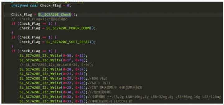
然后对传感器进行设置

外部中断
使用外部中断可以使用用于唤醒mcu,这对设计低功耗的产品很有意义,当传感器超过设定的阈值的时候,那么就会产生一个中断来通知mcu,需要进一步的处理数据,外部中断的配置如下所示:
void exit_wakeup_interrupt_config(void)
{
     /* configure the priority group */
    nvic_priority_group_set(NVIC_PRIGROUP_PRE2_SUB2);

    /* enable the key wakeup clock */
    rcu_periph_clock_enable(RCU_GPIOA);
    rcu_periph_clock_enable(RCU_CFGCMP);

    /* configure button pin as input */
    gpio_mode_set(GPIOA, GPIO_MODE_INPUT, GPIO_PUPD_NONE, GPIO_PIN_0);

    /* enable and set key wakeup EXTI interrupt to the higher priority */
    nvic_irq_enable(EXTI0_1_IRQn, 2U, 0U);

    /* connect key wakeup EXTI line to key GPIO pin */
    syscfg_exti_line_config(EXTI_SOURCE_GPIOA, EXTI_SOURCE_PIN0);

    /* configure key wakeup EXTI line */
    exti_init(EXTI_0, EXTI_INTERRUPT, EXTI_TRIG_FALLING);
    exti_interrupt_flag_clear(EXTI_0);
}
数据处理
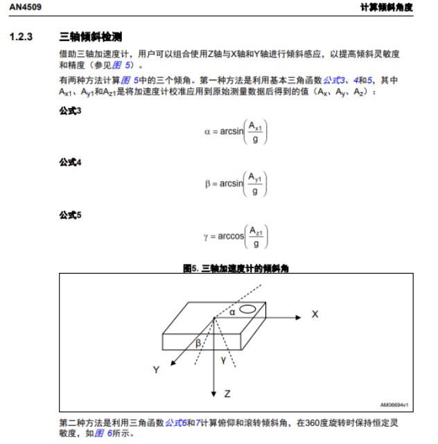
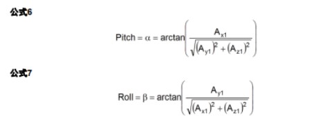
由于我们使用的是三轴传感器,对于姿态位置的计算并不是很精确,因此,此处只用简单角度计算,倾角的计算原理如下


计算代码如下:
#define DEG_TO_RAD(x) ((x) * 0.01745329252)
#define RAD_TO_DEG(x) ((x) * 57.2957795131)
void angle_calculation() {
    double pitch, roll, paw;
    pitch = atan(xyz_mg[X] / sqrt(pow(xyz_mg[Y], 2) + pow(xyz_mg[Z], 2)));
    roll = atan(xyz_mg[Y] / sqrt(pow(xyz_mg[X], 2) + pow(xyz_mg[Z], 2)));
    paw = atan(sqrt(pow(xyz_mg[X], 2) + pow(xyz_mg[Y], 2)) / xyz_mg[Z]);

    printf("[RAD]pitch:%.2f | roll:%.2f | paw:%.2f rn", pitch, roll, paw);
    printf("[DEG]pitch:%.2f° | roll:%.2f° | paw:%.2f° rn", RAD_TO_DEG(pitch), RAD_TO_DEG(roll),
           RAD_TO_DEG(paw));
}