131 1300 0010
想想当你好不容易跟女朋友共度烛光晚餐,却因为蜡烛点没了或打翻着火了,那是一件多么坑爹的事啊!今天为你分享一款自己diy的超自然的烛光蜡烛。
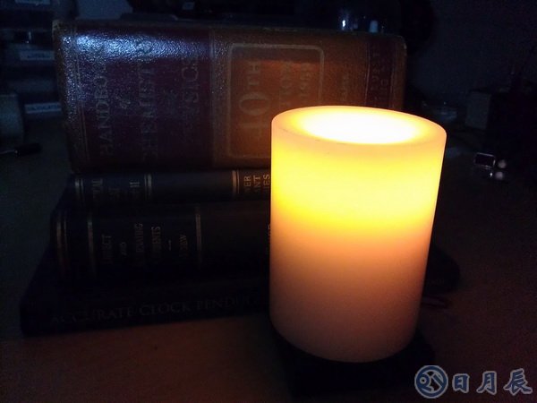
ATtiny 电子蜡烛,皮特•米尔斯开发这个伟大的蜡烛,正如我们图片所见到的一样,但怎样让这蜡烛的光芒像传统的蜡烛一样闪烁呢。
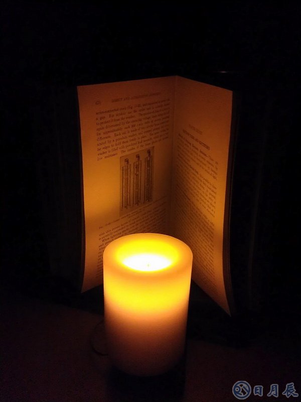
皮特使用一个高亮的LED和一些模拟的辅助软件,这样就使得ATtiny 电子蜡烛的烛光和传统蜡烛拥有一样的闪烁的烛光,并且优于传统蜡烛,因为它不伴有明火的危险。
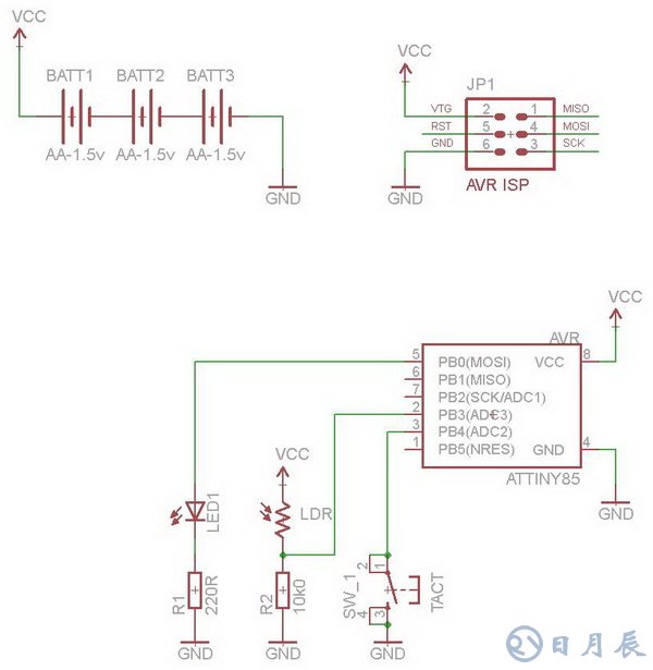
ATtiny 电子蜡烛最难的部分就闪烁神态逼真,所以皮特做了一个蜡烛光检测电阻( LDR )和固定电阻作为一个分压器。这是作为ATTINY85 ADC之中的一个输入端,并离散时间间隔的进行采样。采样速率为100毫秒。然后将采集的8bit的电频值存储到EEPROM中,以便记录蜡烛的闪烁图谱,驱动将其连接的LED、PWM形成通路。在用三节干电池供电。最后您只需编程程序,然后通过开关进行控制。
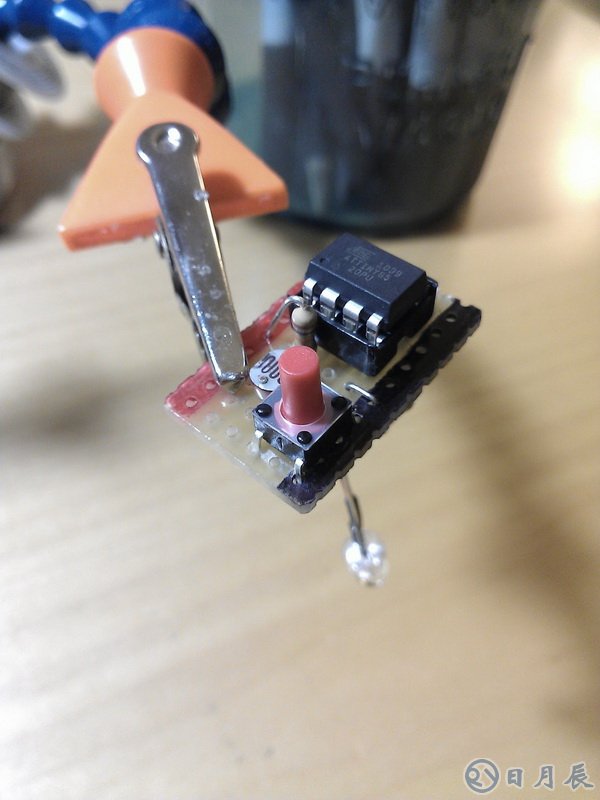
下面是ATtiny 电子蜡烛的电路图
下面是程序的代码以及写入EEPROM的数据
view plainprint?
/*
Program Description: This program reads a light detecting resistor thru an internal ADC and stores the value,
after scaling it, to eeprom. This ADC value is sent to a PWM channel with attached led. This is essentially a data logger
for light and replay by LED. If, if you aim the LDR at a flickering candle during its recording phase, you have a flickering
led candle.
A circuit description and other details can be found at http://petemills.blogspot.com
Filename: ATTiny_Candle_v1.0.c
Author: Pete Mills
Int. RC Osc. 8 MHz; Start-up time PWRDWN/RESET: 6 CK/14 CK + 64 ms
*/
//********** Includes **********
#include
#include
#include
//********** Definitions **********
// LED for flame simulation
#define LED PB0
#define LED_PORT PORTB
#define LED_DDR DDRB
// Light Detecting Resistor for recording a live flame
#define LDR PINB3
#define LDR_PORT PINB
#define LDR_DDR DDRB
// Tactile Switch Input
#define SW1 PINB4
#define SW1_PORT PINB
#define SW1_DDR DDRB
#define ARRAY_SIZE 500 // size of the flicker array
#define SAMPLE_RATE 100 // ms delay for collecting and reproducing the flicker
//********** Function Prototypes **********
void setup(void);
void toggle_led(void);
void program_flicker(void);
void led_alert(void);
void eeprom_save_array(void);
void eeprom_read_array(void);
void scale_array(void);
uint8_t get_adc(void);
uint8_t scale( uint8_t input, uint8_t inp_low, uint8_t inp_hi, uint8_t outp_low, uint8_t outp_hi);
uint8_t is_input_low(char port, char channel, uint8_t debounce_time, int input_block);
//********** Global Variables **********
uint8_t flicker_array[ ARRAY_SIZE ] = { 0 };
uint8_t EEMEM ee_flicker_array[ ARRAY_SIZE ] = { 0 };
int main(void)
{
uint16_t replay = 0;
setup();
eeprom_read_array();
while(1)
{
if( is_input_low( SW1_PORT, SW1, 25, 250 ) )
{
// program the flicker
// after entering and upon completion, a predetermined flash pattern will occur as described in led_alert()
// aim the ldr at a flickering candle or any other light source ( like a laser ) you want to record during this time
// and upon completion the values are stored to eeprom. They are played back immediately as well
// as being recalled from eeprom upon first start up
led_alert();
program_flicker();
scale_array();
eeprom_save_array();
led_alert();
}
// replay the recorded flicker pattern
OCR0A = flicker_array[ replay ];
++replay;
if( replay >= ( ARRAY_SIZE - 13 ) ) // if the end of the stored array has been reached
{
replay = 0; // start again from the beginning
//led_alert();
}
_delay_ms( SAMPLE_RATE );
_delay_ms( 3 ); // ADC Conversion time
}
}
//********** Functions **********
void setup(void)
{
//********* Port Config *********
LED_DDR |= ( 1 << LED); // set PB0 to "1" for output
LED_PORT &= ~( 1 << LED ); // turn the led off
LDR_DDR &= ~( 1 << LDR ); // set LDR pin to 0 for input
LDR_PORT |= ( 1 << LDR ); // write 1 to enable internal pullup
SW1_DDR &= ~( 1 << SW1 ); // set sw1 pin to 0 for input
SW1_PORT |= ( 1 << SW1 ); // write a 1 to sw1 to enable the internal pullup
//********** PWM Config *********
TCCR0A |= ( ( 1 << COM0A1 ) | ( 1 << WGM01 ) | ( 1 << WGM00 ) ); // non inverting fast pwm
TCCR0B |= ( 1 << CS00 ); // start the timer
//********** ADC Config **********
ADMUX |= ( ( 1 << ADLAR ) | ( 1 << MUX1 ) | ( 1 << MUX0 ) ); // left adjust and select ADC3
ADCSRA |= ( ( 1 << ADEN ) | ( 1 << ADPS2 ) | ( 1 << ADPS1 ) ); // ADC enable and clock divide 8MHz by 64 for 125khz sample rate
DIDR0 |= ( 1 << ADC3D ); // disable digital input on analog input channel to conserve power
}
void toggle_led()
{
LED_PORT ^= ( 1 << LED );
}
uint8_t is_input_low( char port, char channel, uint8_t debounce_time, int input_block )
{
/*
This function is for debouncing a switch input
Debounce time is a blocking interval to wait until the input is tested again.
If the input tests low again, a delay equal to input_block is executed and the function returns ( 1 )
*/
if ( bit_is_clear( port, channel ) )
{
_delay_ms( debounce_time );
if ( bit_is_clear( port, channel ) )
{
_delay_ms( input_block );
return 1;
}
}
return 0;
}
uint8_t get_adc()
{
ADCSRA |= ( 1 << ADSC ); // start the ADC Conversion
while( ADCSRA & ( 1 << ADSC )); // wait for the conversion to be complete
return ~ADCH; // return the inverted 8-bit left adjusted adc val
}
void program_flicker()
{
// build the flicker array
for( int i = 0; i < ARRAY_SIZE; i++ )
{
flicker_array[ i ] = get_adc();
_delay_ms( SAMPLE_RATE );
}
}
void led_alert()
{
// this is a function to create a visual alert that an event has occured within the program
// it toggles the led 10 times.
for( int i = 0; i < 10; i++ )
{
OCR0A = 0;
_delay_ms( 40 );
OCR0A = 255;
_delay_ms( 40 );
}
}
void eeprom_save_array()
{
for( int i = 0; i < ARRAY_SIZE; i++ )
{
eeprom_write_byte( &ee_flicker_array[ i ], flicker_array[ i ] );
}
}
void eeprom_read_array()
{
for( int i = 0; i < ARRAY_SIZE; i++ )
{
flicker_array[ i ] = eeprom_read_byte( &ee_flicker_array[ i ] );
}
}
uint8_t scale( uint8_t input, uint8_t inp_low, uint8_t inp_hi, uint8_t outp_low, uint8_t outp_hi)
{
return ( ( ( input - inp_low ) * ( outp_hi - outp_low ) ) / ( ( inp_hi - inp_low ) + outp_low ) );
}
void scale_array()
{
uint8_t arr_min = 255;
uint8_t arr_max = 0;
uint8_t out_low = 20;
uint8_t out_high = 255;
// find the min and max values
for( int i = 0; i < ARRAY_SIZE; i++ )
{
if( flicker_array[ i ] < arr_min )
arr_min = flicker_array[ i ];
if( flicker_array[ i ] > arr_max )
arr_max = flicker_array[ i ];
}
// now that we know the range, scale it
for( int i = 0; i < ARRAY_SIZE; i++ )
{
flicker_array[ i ] = scale( flicker_array[ i ], arr_min, arr_max, out_low, out_high );
}
} igh );
}
} igh );
}
}
}
}
}
}
}
} }
} }
} }
}

